(I love how smooth this table ended up - that shows me that my bit is square to the machine. Had the bit not been square, it would have created "steps" or grooves from the lower part of the scribed circle.)
I have also generated code to manually mill square surfaces - mainly to level the table. The g-code is a loop that, using relative not absolute x/y values, cuts concentric squares until the surface is fully covered.
The next step in the challenge is to mill a pocket. A pocket is like milling out a flat surface and tracing a shape all in one operation. And in theory, if I wanted to just mill out a square pocket, I could probably hand code the operation. But what about more complex pockets, with curves or other complex features? That's where software becomes necessary (unless you are a sucker for punishment - cause doin' it manually is not going to be trivial).
There are 2 major classes of software in the process from conception to construction. CAD & CAM. CAD stands for Computer-aided Design and CAM stands for Computer-aided Manufacturing. To get good results both are required.
A CAD program is used to draw the shape in a human appreciable way (a wire frame / 3D picture). For this I have been using Google's Tremble's Sketchup.
A CAM program is used to convert the picture into g-code that the milling software runs. To cut 2D shapes designed in Sketchup there are direct plugins that will produce the g-code - I have used Phlatscript with a lot of success. For pocket milling, the options get harder to determine. This is not an easy problem to solve, and there are a lot of (possibly very good) solutions that will cost a lot of money. I am looking for something to fit my budget (ie: free).
Two major options kept coming up in my searches - Freemill and PyCAM. Freemill is a crippleware version of a professional CAM package. If you are milling soft material, this package may work well for you. However, what it does not do is roughing passes or multiple passes in general (hence my assessment that it's crippleware).
PyCAM is an opensource tool that is not perfect. I am struggling to make it work properly. It is possible my 'test' project was a bit too complex for a first try.
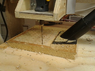
My test project is a vacuum hold down table for milling PCB boards. The plan was to take a 3/4" board, mill a square pocket on the bottom with support structures and a circle on one end to insert the vacuum hose. I also put the air holes from the pocket through to the working surface in my drawing - and I think this confused PyCAM.
What I learned was that I need to make the pocket in 2 steps. The first a roughing pass and then the final pass.
PyCAM's roughing pass algorithm is a raster scan of the area to be hollowed out. Choose X/Y carefully - the first time I picked wrong, and the mill was going to be going up and down a lot! (Which would waste a ton of time.) The second mistake I made was have the roughing pass get to close to the finished edge - the result was that the finishing pass was too far from the edge and did not really clean anything up.
The finishing pass does not hollow out the pocket! All it does is trace the edge to clean up from the roughing pass. I was not understanding this. In part this was due to it taking hours to render - I found out that my 1/8" air holes were to complex to finish with a 1/8" bit. Once I gave up finishing that deep, the finishing step finished in a much shorter time frame.
In the end, I managed to generate some g-code files that I thought would work. I only had a 5/8" board, so the mill spent a bunch of time milling out the air! I also found out that I had set the feed rate way to fast, and had to slow down the maximum speed of the mill - this meant that the rapids between cut were not so rapid.
I also continued to struggle with the cheap rotary tool letting the bit slip. Turns out the collet / chuck design is garbage. The collet could pivot in the chuck with enough force (which when a 1.5" bit is ripping along there is enough force). Once it pivots, the 1/8" bit is now carving out a 1/4" circle - DOUBLE the planned amount. The additional load bogs the machine down and drags the bit out of the spindle and into the material. (At great risk of damage to bit, machine, operator and final product). I changed back to the older, better quality, but sadly wearing out, rotary tool and finished the job without any further issues
Roughing pass took 2-3 hours to mill, the finishing pass took 1/2 hour. Then I milled off the top in a few minutes, and manually drilled the holes in about 10-15 minutes.
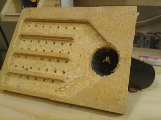
In the picture you can see the edges from the rastor scanned roughing pass. Unfortunately the finishing pass cannot be appreciated from this job. The nasty crack across the bottom right corner was from undoing my first attempt at gluing a hose attachment - had nothing to do with the milling process.
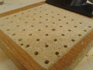
For completeness, this is what the table looks like when in place. The top square was milled using my table leveling program. The air holes were manually drilled (using the CNC machine, but driving the bit manually using the keyboard).