January 2010 Archives

Inexpensive 400A DC Clamp meter

|
| Comments (0)
Canadian Tire of all places sells a must have tool for electric RC builders and pilots. A DC current meter that can measure over 10A. This is a clamp style meter (funny that the site calls is a Clap meter). It retails for $59.99 which is decent enough, but this week it went on sale for $20.99!!! Less than $25 taxes in gets a tool that can measure up to 400A of DC current! (BTW, it needs 2 x AAA batteries - the first time I've bought a meter that did not include batteries...)

DC Clamp Meter

I saw Mark from Cellar Dweller use one about a year ago to balance the up / down thrust of an electric heli and it immediately went to the top of my wish list.

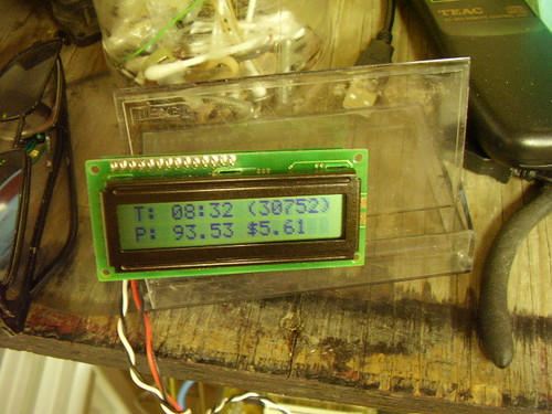
So I just picked one up tonight and tried it out. It's no bazillion dollar Fluke(tm), but for $21 it works quite well. Measured the current draw on one of my planes @ 13.6A (11.1V - 150Watts!). (I think I saw a 16A on the first test, but too much stuff was blowing around the shop, and the battery in the plane was not fully charged.)

One a side by side test with an inline current meter (also Mastercraft), the inline measured 3.08A and the clap :-) meter measured 3.2A.

AC current test was measured while my furnace was running. The reference meter was a cheap (picked up on sale for less than $15 taxes in) PowerFist (Princess Auto) AC clamp current meter. It read 40.1A while the Mastercraft read 38.9A.

That's acceptable tolerance for my needs.

Furnace stats online

|
| Comments (0)
So I've been working on my furnace monitoring kit. And now I have basic weather logging enabled. I am fetching climate data from Environment Canada and adding it to a logging tool called RRD. This is a clever fixes size logging data store. It is meant for recording data on fixed time intervals. In my case I'm recording cycle counts, kWh used and outside temperature once every hour. It spits out graphs like this (hourly for 7 days):


I have created a full page to track weekly, monthly and annual usage.

There is a script (furnace.pl) constantly running that pings the microcontroller every second which returns the current status of the furnace (heating or not).

My crontab looks like this:

0 5 * * * /home/me/furnace/logparse.pl
5 5 * * * /home/me/furnace/hourly.pl
10 5 * * * /home/me/furnace/catchup.pl
20 5 * * * /home/me/furnace/enterdata.sh #legacy - generated by catchup.pl
0 6 * * * /home/me/furnace/fetchclimate.pl
5 6 * * * /home/me/furnace/graph.sh
10 6 * * * ftp -inv < /home/me/furnace/ftpscript #upload graphs to flyinglow.ca/furnace

These are works in progress. You can follow my furnace online (a_furnace).
0 0-23 * * * /home/me/furnace/twit.pl #tweet the daily usage up to the hour
0-59 * * * * /home/me/furnace/lcdstatus.pl #update an LCD display (and spin some servos)

Here is a zip archive of the scripts I created. They still need some polishing.

scripts.zip

DIY Humidifier

|
| Comments (0)
Ok, so last fall I had too much humidity (cool, damp summer), and now I don't have enough. Life in an older house in Manitoba....

So - one of the things I have done in the past is to reclaim the warm, moist air from the clothes dryer in winter. In my previous house, I had simply cut a bunch of slots in a 5 gallon pail, lined it with a piece of bulk furnace filter material and fed the dryer hose in through a hole in the lid. That worked, but was in the way and not easy to maintain.

This year, I bought a special valve for redirecting the warm, moist air back into the house. To trap the lint dust, I initially tried a water pail sold for that purpose - it's a small (2-3 litre) bucket that you fill with water. The hose is attached to the top and blows over the water - which is supposed to trap the lint dust. I wasn't impressed.

I liked the furnace filter idea better.

So, with the help of a friend who had way better wood working tools than I do, I built this fancy box that holds a 20x20x1 furnace filter.

In house dryer vent filter 1

In the winter I'll set the valve to redirect air into the house, and in summer it gets set to send the hot air outside.

In house dryer vent filter 1

When the filter gets full, its easy to slide out and replace.

Update (1/19/10): Humidity on laundry day jumped from just below 50% (we have had a mild spell which tends to not dry the house out as much) to nearly 60% by end of day. It has since (24 hours later) fallen to about 55%.

My furnace goes tweet!

|
| Comments (0)
So I probably should have spent my holidays getting my planes ready to fly, or my bike cleaned up and ready to ride (I have gained way to much weight since parking the bike at the end of October) - but instead, I worked on building a monitor for my furnace. I would like to know things like, how much money am I really saving by setting the thermostat back at night? How often does the furnace run? How long does it take the house to cool off at night before (or if) the furnace kicks in? and more!

I started a few weeks back and nearly had a permanent set back when one of the voltage regulator circuits I built blew up. Once I realized nothing vital was ruined, it was back at it. The circuits were completed - at least the prototype. Starting with the revamped power supply.

Power station

I made a few changes. Starting with the capacitor. Since blowing up a couple smaller ones, I researched proper sizing and most recommendations were to double the rating for safety - that is, 24VAC rectified into 35VDC meant the capacitor that filtered the DC supply should be rated for 70V. I actually had 1 cap that fit the bill. It is an old 330V 200uF cap from a camera flash I took apart almost 20 years ago (NEVER THROW ANYTHING OUT!). Next in the circuit was a voltage divider. With the 7812 damaged, I was down to a 7805 which would be working even harder to drop the voltage. Voltage dividers are a simple circuit consisting of 2 resisters in series. If the resisters have the same value, the voltage as measured in the middle is exactly half the supply voltage. I used 1.9K and 5.6K/3 (1.8K) - which results in a current draw of 10mA. Do not forget to take power dissipation into account! 10mA @ 35VDC is 1/3Watts. I used 1/2Watt resistors, and for the first resister I actually used 3 in parallel to share the load (the values where increased by 3 times). This circuit runs nice and cool.

Black box

The signal from the furnace / thermostat is also 24VAC. Not something to feed straight into a micro-controller. To isolate the signal and produce a more managable voltage, I used paper sensors from an old laser printer. These have an ir LED and photosensor nicely lined up. A resistor and LED in series with the line from the thermostat dropped the current to a safe level for the opto-coupler. I put a cap across the opto-coupler LED to try and smooth the pulses, but still needed to put code in place to handle the 60Hz flicker. This is packaged into a project box. The notation is C-common, Y-yellow (cooling/AC), W-white (heating), 5- +5VDC, G-ground.

Usage monitor

The microcontroller listens on a serial line for a poke (the 'A' character) from the PC and returns a 1 or 2 if the furnace is on or off (0/1 caused Perl to think NULL/1 - sigh). Perl scripts on my shop linux box poke the microcontroller every second, log the results, summarize the information and update the LCD display every minute. As a bonus, every hour a tweet is sent out. Both the LCD display and tweet contain the total runtime of the furnace and the approximate power consumed since midnight.

A note about the power consumption. The furnace is electric. It has 3 x 4,800 watt elements that come on one at a time 60 seconds apart. So the scripts take the staging into account. Often, during the day the furnace only runs for 180 seconds at a time or less. Also, here in Manitoba the cost of power is currently $0.063 / kWh (1/4/10). I believe I have the scripts using $0.06 / kWh.