January 2013 Archives

Installing the Little CNC Z-Axis

|
| Comments (0)
The new axis is complete, installed and tested - yeah!

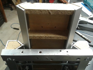
Where did I leave off, oh yeah, the spindle mount and linear bearings where built. Next step was to add the actuator to the assembly.

CNC z-axis installation
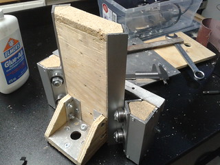
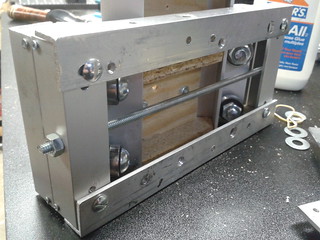
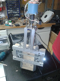
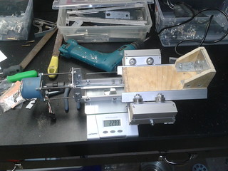
Using some lighter weight angle aluminum (3/4"x3/4"x1/16"), I constructed risers. A plate across the top holds the bearing through which a threaded rod with a locking nut rests. The stepper is reused from the big CNC in the man-cave (currently awaiting a much needed upgrade). It is a 5V 1A 35oz stepper - adequate, but barely. A spider coupler joins the threaded rod to the stepper, which is held above the bearing plate by 4 threaded rods and a collection of nuts (one more if you include me).

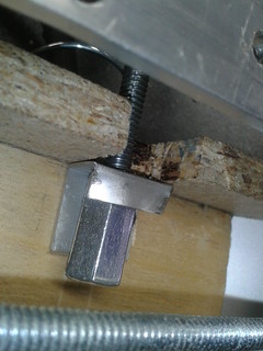
Barely visible near the middle of the bottom cross brace is a screw that extends into the assembly. One of (many) holes nearby complements that screw - together they will push and pull the bottom of the assembly out to provide an adjustment to help square the bit to the table.

CNC z-axis installation

Attaching the threaded rod to the spindle holder was a matter of crimping some of the light gauge aluminum around a 1/4" union and fastening the aluminum to the top of the holder. The better aligned this is with the stepper the faster things can move without binding. I left a fair bit of play in the spider coupler / weight bearing at the top that I am getting a respectable travel rate.

CNC z-axis installation

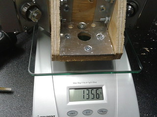
The whole thing weighs more than the previous design. 2.3 kgs is without the spindle. With the spindle it weighs 2.8kgs, which is about a full kg more than the current assembly.

CNC z-axis installation

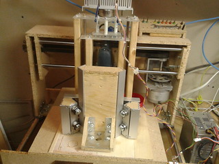
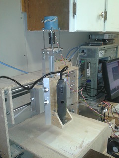
And here it is installed! Some tweaking and adjusting, but so far it is very square to the table. Total travel is almost 4". Feedrate is 9-10ipm (which is slow, but compared to the 3-4.5 that I was getting on the previous model, much better!). I have gained a couple inches on the X axis due to the back of the assembly NOT interfering with the gantry, so that's good. However, I have lost a couple inches on the Y axis because the Z-axis assembly sticks out further - that is not so good.

Whipping around at 100ipm there is a lot of bouncing / shaking. The whole machine needs a lot of stiffening - so for now, I'll run a lot slower.

I did run into an interesting problem - I put a brand new, long cutting tool and did a small test run. The collet slipped and let go of the tool, causing some deep gauging in the table. I have since read up on why it is important to clean the oil off the cutters before using them....

Little CNC Z-axis

|
| Comments (0)
I am trying to rebuild a better Z-Axis for the smaller CNC machine. My requirements are:

  1. Increased travel. The current axis has 3/4" of travel, which limits both the depth of cuts, the size of the material I can cut and even the length of bits I can use.
  2. Better adjustments for squareness. The current axis has effectively none, and the bit is not square to the milling surface. Not a big deal for some engravings, but not very good when trying to cut out parts.
  3. Easier tool changing capability. The current assembly makes it challenging to change tools. There's too much structure around the collet.
  4. Reduced backlash. I want the bearings / slides / whatever to be tight. No play or slop.
  5. Light weight. The gantry style machine is flinging a lot of weight and adding more only reduces overall performance.
My first serious overhaul attempt was to have a pair of bearings squeeze a steel rod. The idea was that by squeezing the bearings, I could adjust for tension and even angle. The problem was the bearing were not only rolling, but also sliding as the rod went past (think of your car tire rubbing against the curb when you park too close). The friction was too much.

My current attempt is the common angle aluminum linear bearing assembly seen all over the net.

CNC z axis

This design gives a lot of travel, is rock solid (so far) and enables easier tool changing.

CNC z axis

It is 2" wider than the current stand.

Little CNC Z axis.

And it does weigh a fair bit, so I'm not sure how much I've improved there.

CNC z axis

The threaded rod across the back and the slots in the cross bars allow for tension adjustment and some squaring of the tool to the surface.

CNC z axis

These ribs are how the angle aluminum is mounted to the cart.

Left to do:

Adding a stepper motor with threaded rod and nut for motion control. I will need to cut/drill into the ribs to make room for the rod and the nut will be mounted on the bottom rib. Some form of structure to mount the stepper motor to. For now I will probably use a basic 1/4" 20TPI threaded rod. This will limit the speed of the vertical travel, but is simple.

Nortel QxBIXxxx stuff for sale

|
| Comments (0)
Cleaning up the shop, I came across a small assortment of BIX tools and accessories.